|
There's something rather futuristic
about talking 'over' a laser beam, which is what this
inexpensive project allows. It will easily give a communication
distance of several hundred metres, and with a parabolic
light reflector, up to several kilometres. It transmits
high quality audio and the link is virtually impossible
for anyone else to tap into.
In the February 1993 issue, we described a laser beam
communicator project developed by Oatley Electronics.
It was an extremely popular project, but this latest
version not only makes the device better and simpler,
but cheaper as well. Unlike the previous version, a
visible laser diode (5mW 65Onm) is used as the transmitter.
This makes alignment between the transmitter and receiver
much simpler, as you can now see the beam. As well,
the laser has a greater output power. The circuitry
is also simpler, and uses basic components.

As before, there are two sections: the transmitter
board and the receiver board, both powered by a separate
9V battery or a fixed voltage power supply, depending
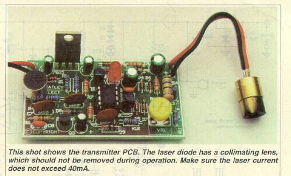
on your needs. The transmitter board has an electret
microphone module at one end, and the laser diode at
the other end. The electronics modulates the intensity
of the laser beam according to the output of the microphone.
The laser diode has an inbuilt collimating lens, and
is simply a module that connects to the transmitter
board. The previous design required brackets for the
laser diode assembly.
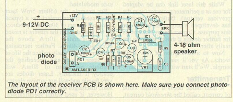
The receiver uses a photodiode as the receiving element,
and the onboard amplifier powers a small 4-36 ohm speaker.
This board is therefore a high gain amplifier with a
basic audio output stage.
But what about results - are they better? Sure. Because
this design uses a higher power (and visible) laser
beam, the range is improved, and alignment is easier
and not all that critical, especially over a few hundred
metres. The quality of sound transmit ted by the link
is quite surprising.
As a simple test, we set up the prototype with the transmitter
microphone near a radio. The received sound was clear
and seemed to cover the full audio bandwidth. We haven't
tried feeding an audio signal directly to the transmitter,
but that will undoubtedly give even better results.
So clearly, this project is ideal for setting up a speech
channel between two areas, say adjacent houses, or offices
on opposite sides of the street. Or you could use it
as a link between the work shop and the house. For duplex
(two way) communication, you'll obviously need two laser
'channels'.
An important feature of transmission by laser beam is
privacy. Because a laser beam is intentionally narrow,
it's virtually impossible for someone to tap into the
link without you knowing. If someone intercepts the
beam, the link is broken, signalling the interception.
Fibre-optic cables also have high security, as it's
very difficult to splice into the cable without breaking
the link. However it's theoretically possible; so for
the highest security, you probably can't beat a line-of-sight
laser beam.
You can also use an infrared laser, as in the previous
project. While this gives even better security, as you
can't see the laser beam without special IR sensitive
equipment, it also makes alignment more difficult. (An
IR laser diode is available for the project; see end
of article for details.)
fig.1 (above): The circuit for
the transmitter. The output of the microphone is amplified
by IC2a, which feeds the modulating transistor Q1, which
varies the laser current according to the signal. The
quiescent current of the laser diode is set by VR1.
The Receiver
fig2 (above): The circuit for the receiver, where light
from the transmitter is detected and converted to a
voltage by the photodiode. The signal is amplified by
Q1 and IC1, which drives the speaker.
Where the transmission distance is no more than metre
of so, a LED (or two for increased power) can be substituted
for the laser diode. For instance, where the link is
being used for educational purposes, such as demonstrating
fibre-optic coupling, or the concept of communication
over a light beam. Obviously the security of the transmission
is much lower as LEDs transmit light in all directions.
While this laser link can be adapted for use as a perimeter
protector (as in the previous version), Oatley Electronics
has developed a project especially for this purpose.
Contact Oatley Electronics for further details if that
is what you are really after.
Now to a description of how it all works. As you'll
see, it's really very simple. We'll start with the transmitter...
Transmitter
A laser diode needs a certain value of current, called
the threshold current, before it emits laser light.
A further increase in this current produces a greater
light output. The relationship between output power
and current in a laser diode is very linear, once the
current is above the threshold, giving a low distortion
when the beam is amplitude modulated. For example, the
65Onm 5mW laser diode used in this project has a typical
threshold current of 3OmA and produces its full output
when the current is raised by approximately 1OmA above
the threshold to 4OmA. Further increasing the current
will greatly reduce the life of the laser diode, and
exceeding the absolute maximum of 8OmA will destroy
it instantly. Laser diodes are very fragile and will
not survive electrostatic discharges and momentary surges!
However, if used within specifications, the typical
life of one of these lasers is around 20,000 hours.
In the transmitter circuit (Fig.1) the laser diode is
supplied via an adjustable constant-current source.
Since the lasing threshold also varies with temperature,
a 68ohm NTC thermistor is included to compensate for
changes in ambient temperature. Note that the metal
housing for the laser diode and the lens also acts as
a heatsink. The laser diode should not be powered without
the metal housing in place. The quiescent laser diode
current is controlled by Q2, in turn driven by the buffer
stage of 1C2b. The DC voltage as set by VR2 appears
at the base of Q2, which determines the current through
the transistor and therefore the laser diode. Increasing
the voltage at VR1 reduces the laser current. The setting
of VR1 determines the quiescent brightness of the laser
beam, and therefore the overall sensitivity of the system.
The audio modulation voltage is applied
to the cathode of the laser diode, which varies the
laser current around its set point by around +/-3mA.
The modu- lation voltage is from the emitter of Q 1,
which is an emitter follower stage driven by the audio
amplifier stage of 1C2a. Diodes D4 to D7 limit the modulating
voltage to +/-2V, while C4 and C5 block the DC voltages
at the emitter of Q 1 and the cathode of the laser diode.
The audio signal is coupled to the laser diode via R10,
which limits the maximum possible variation in the laser
diode current to a few milliamps

LED1 gives an indication of the modulating voltage.
Diodes D2, D3 and resistor R8 limit the current through
the LED and enhance the brightness changes so the modulation
is obvious. The LED flickers in sympathy with the sound
received by the microphone, giving an indication that
a modulating volt- age is present
The inverting amplifier of 1C2a includes
a form of compression, in which the output level is
relatively constant and independent of how soft or loud
the audio level is at the microphone. This is achieved
by FET Q3 and its associated circuitry.
The cascaded voltage doubler of C9, D8, D9 and C8 rectifies
the audio signal at the emitter of Ql, and the resulting
negative DC voltage is fed to the gate of Q3. An increase
in the audio signal will increase the negative bias
to Q3, increasing its drain-source resistance. Because
the gain of 1C2a is determined by R7 and the series
resistance of R5 and Q3, increasing the effective resistance
of Q3 will lower the gain.
Since the compression circuit takes time to respond,
the clamping network of D4-D7 is still needed to protect
against sudden voltage increases. This system is rather
similar to the compression used in portable tape recorders.
The electret microphone is powered
through R1 and is coupled to the non inverting input
of 1C2a via C6. This input is held at a fixed DC voltage
to give a DC output to bias Ql.
The supply voltage to the transmitter circuit is regulated
by ICI, a 5V three terminal regulator.
Receiver
The transmitted signal is picked up
by the photo detector diode in the receiver (shown in
Fig.2). The output voltage of this diode is amplified
by the common emitter amplifier around Ql. This amplifier
has a gain of 20 or so, and connects via VRI to ICI, an
LM386 basic power amplifier IC with a gain internally
set to 20.
This IC can drive a speaker with a resistance as low as
four ohms, and 35OmW when the circuit is powered from
a 9V supply. Increasing the sup- ply voltage will increase
the output power marginally.
The voltage to the transistor amplifier stage is regulated
by ZD I to 5.6V, and decoupled from the main supply by
R2 and C2. Resistor R3 supplies forward current for the
photodiode. (Incidentally, the photodiode used for this
project has a special clear package, so it responds to
visible light, and not just infrared.)
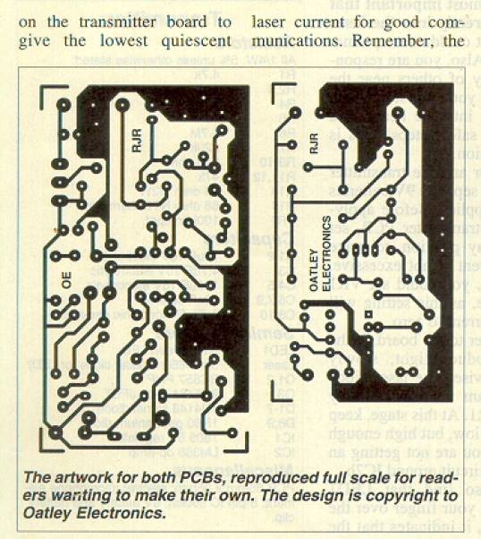
Construction
As the photos show, both the transmitter and the receiver
are built on silk- screened PCBS. As usual fit the resistors,
pots and capacitors first, taking care with the polarity
of the electrolytics. IC sockets are not essential,
although servicing is obviously made easier if they
are used. In which case, fit these next, followed by
the transistors, diodes and the LED.
Take care to use the right diodes for D8 and D9. These
are larger than the 1N4148 types, and have two black
bands (the cathode end) around a glass package. Note
that the regulator IC has the tab facing outwards.
The photodiode is mounted directly on the receiver PCB.
When first mounted, the active side of the diode (black
square inside the package) will face towards the centre
of the board. You then bend the diode over by almost
180' so the active surface now faces outwards.
The polarised microphone element solders directly to
the transmitter PCB. The negative lead is marked with
a minus sign and is the lead that connects to the metal
case.
The laser diode is also polarised, and has three leads.
Of these, only two are used, shown on the circuit as
pins 2 (cathode) and 3 (anode). Take care when soldering
the laser in place, as too much heat can destroy it.
The diode can be mounted on the board, or connected
with leads to it.
Finally, connect the speaker and 9V battery clips, then
check over the boards for any soldering errors or incorrectly
installed components.
Testing
First of all, it's most important that you don't look
directly into the laser beam. If you do, it could cause
perma- nent eye damage. Also, you are respon- sible
for the safety of others near the laser, which means
you must stop others from also looking into the beam,
and take all necessary safety steps. This is covered
by legislation.
Both the receiver and the transmitter can be powered
by separate 9V batteries or suitable DC supplies. Before
apply- ing power to the transmitter PCB, set VRI to
its halfway position, to make sure the laser current
is not excessive. To be totally sure, you could set
VRI fully anticlockwise, as this setting will reduce
the laser current to zero.
Then apply power to the board. If the laser doesn't
produce light, slowly adjust VRI clockwise. The laser
diode should emit a beam with an intensity adjustable
with VRI. At this stage, keep the beam intensity low,
but high enough to clearly see. If you are not getting
an output, check the circuit around IC2b.
You should also find that LED 1 flickers if you run
your finger over the microphone. If so, it indicates
that the amplifier section is working and that there's
a modulation voltage to the laser diode. You won't see
the laser beam intensity change with the modu- lating
signal.
To check that the system is working, place the two PCBs
on the workbench, spaced a metre or go apart. You might
need to put a sheet of paper about 2Omm in front of
the photodiode to reduce the intensity of light from
the laser beam. Set the volume control of the speaker
to about halfway. If the volume control setting is too
high you'll get acoustic feedback.
Move the laser diode assembly so the beam points at
the receiver's photodi- ode. It's useful to adjust the
beam so it's out of focus at the photodiode, to make
alignment even easier. You should now be able to hear
the speaker reproducing any audio signal picked up by
the microphone. When the receiver and transmitter are
in close range, the strength of the beam can cause the
receiver to respond even if the laser beam is not falling
on the photodiode.
Setting up a link
Once you've tested the link, you'll probably be keen
to put it to use. For a short link of say 100 metres,
all you need do is position the receiver so the laser
beam falls on the photodiode. Once the link is established,
adjust VRI higher the laser current, the shorter will
be its life.
If you have an ammeter, connect it to measure the current
taken by the trans- mitter board. Most of the current
is taken by the laser, so adjust VRI to give a total
current consumption of no more than 45mA.
Also, focus the laser so all of the beam is striking
the photodiode. At close range, there's probably no
need to focus the beam. In fact, because of the high
output power (5mW) of the laser diode, excellent results
will be obtained over reasonably short distances (20
metres or so) with rough focusing and quiescent current
adjust- ments. But the longer the dis- tance between
the transmitter and the receiver, the more critical
the adjustments. For example, for distances over 20
metres, you might have to put a piece of tube over the
front of the photodi- ode to limit the ambient light
falling on it. This diode is responsive to visible light,
so a high ambient light could cause it to saturate.
For very long distances, say a kilome- tre, you'll probably
need a parabolic reflector for the laser beam, to focus
it direct- ly onto the photodiode.
For short ranges (a metre or so), or for educational
or testing purposes, you can use a conventional red
LED. Adjust the quiescent current with VR1. The light
output of a LED is not focused, and simply spreads everywhere,
so a reflector might help the sensitivity. Warnings
The laser diode in this project is a class 3B laser
and you should attach a warning label to the trans-
mitter. Labels will be sup- plied by Oatley Electronics.
Remember that, as for any hazardous device, the owner
of a laser is responsible for its proper use.
Transmitter:
Resistors
All 1/4W, 5% unless otherwise stated:
Rl 4.7k
R2,3 1 00k
R4 68k
R5 10k
R6 4.7M
R7 220k
R8-1 0 220 ohm
Rl 1,12 47k
R13 56 ohm 1/2W
R14 68 ohm NTC thermistor
VR1 1 00k trimpot
Capacitors
Cl,2 1OuF 16V electrolytic
C3 4.7uF 16V electrolytic
C4,5 10OuF 16V electrolytic
C6,7,9 68nF ceramic
C8,1 0 0.47uF monolithic ceramic
Semiconductors
LED1 5mm green LED
Laser 5mW/65Onm laser diode (or LED)
Ql,2 BC557 PNP
03 2N5484 N-ch JFET
Dl-7 1N4148 signal diode
D8,9 1 N60 germanium diode
lci 7805 5V regulator
1C2 LM358 op-amp
Miscellaneous
PCB 65mm x 36mm; electret microphone element;
8-pin IC socket; 9V battery and battery clip.
Receiver:
Resistors
All 1/4W, 5% unless otherwise stated:
Rl 680 ohm
R2 22 ohm
R3 4.7k
R4 39k
R5 3.gk
R6 10k
R7 1 k
R8 220 ohm
Rg 4.7 ohm
VR1 50k trimpot
Capacitors
Cl,2,5,7 10OuF 16V electrolytic
C3,4 1 uF 16V electrolytic
C6 15nF polyester
Semiconductors
Qi BC549 NPN
ici LM386 power amp
ZD1 5.6V 40OmW zener
Miscellaneous
PCB 36mm x 64m; photodiode with clear
casing; 9V battery and battery clip, 4-16 ohm
speaker; 8-pin IC socket.
:: Copyright to this project is retained by
NeoLuc ® Electronics. :: Contact: NeoLuc@NeoLuc.Ro
|